Design Skills
- Design for Manufacturing
- Design for Assembly
Dewalt Battery Holder
The product started as solution to the problem of organizing batteries in form that allows quick mounting and easy access. The product started with a customer focus to ensure it added value to the end users. The major way this was achieved was minimizing the work to mount it since competitors were using 3+ screws to mount 1 battery. This meant a thick back was required to direct the load back to mounting points
Single holder annotated with major design features:
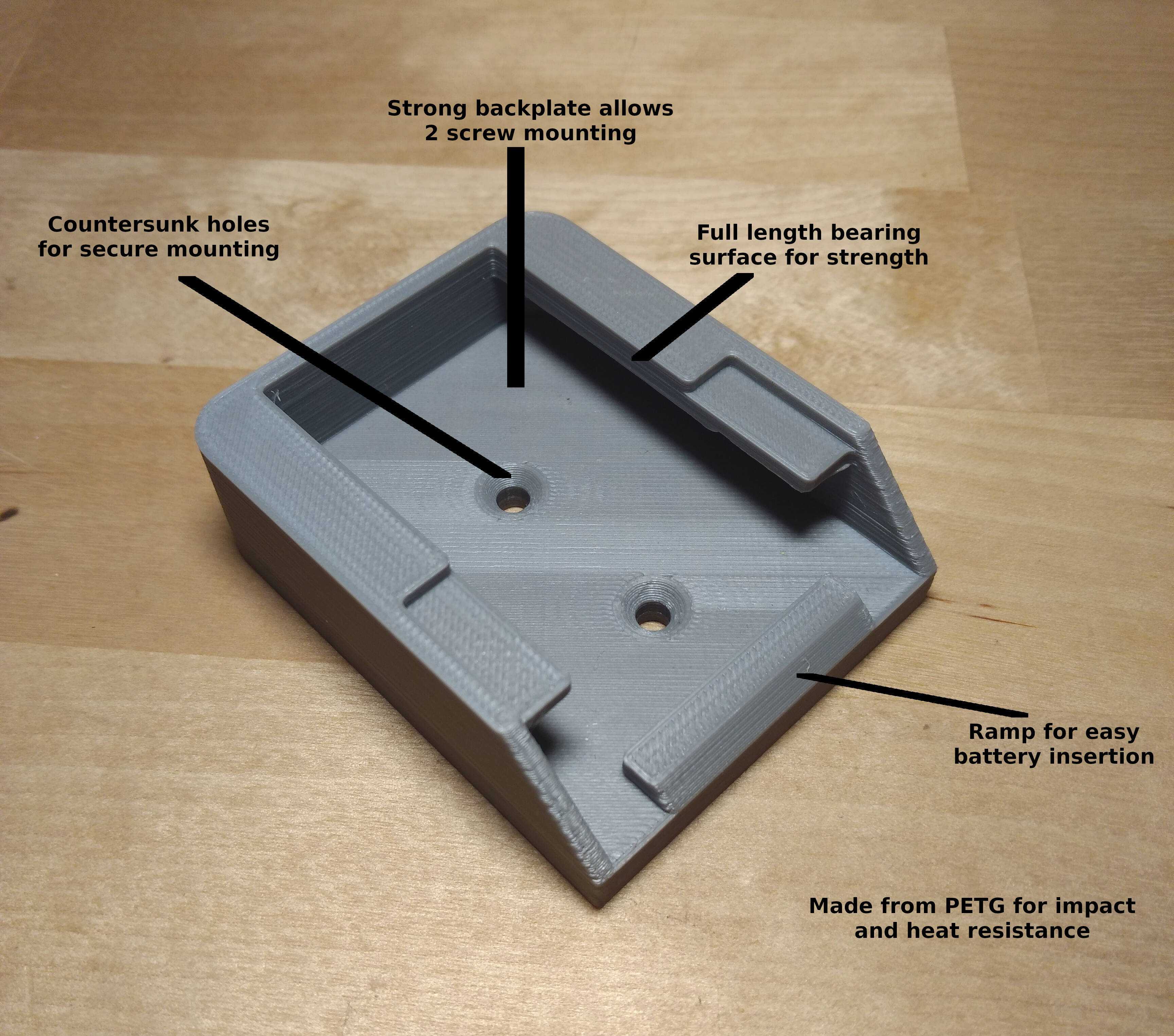
The part was designed using FreeCAD to create a parametric 3D model while refining the fitment based on prototype prints that were used to check fitment with the batteries. The max stress on the part in all orientations were estimated using hand calcuations. The material properties had to be estimated using data from a Makerbot study on pritned parts to account for the interlaminar strength.
The product was optimized for 3d printing speed by leaving the back as a box to take advantage of infill speeds being 2.75 times faster than perimeters. The corners in the xy plane were filleted for an additional 10 minute gain. The thin wall portions were improved by leveraging the parametric model so the wall thickness were multiples of the perimeter extrusion width. Modifier meshes in Slic3r were then used to change print characteristics on the target areas only increasing strength, consistency and print speed.
Results:
Dual holders were well liked by customers, but sales numbers were hindered by consistent issues with the 3d printers bought for production.
Differential Mounts
This part was created for the WSU Formula SAE team.
The part was designed to:
- Hold axles in correct alignment relative to wheel
- Mate to differential
- Mate to tripod joints
- Withstand drivetrain loading
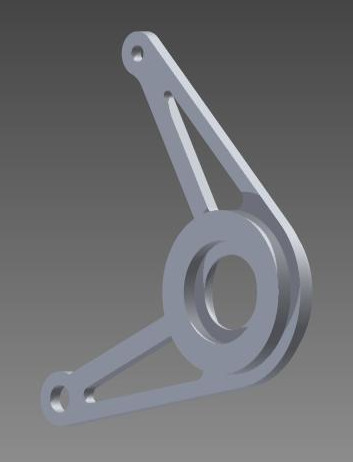
The part was designed using Solidworks to create a parametric 3D model. The max loads on the part were determined using hand calcuations. Iterations of the model were run in Solidworks Simulation until the part was optimized with the least amount of material needed to resist the loading.
The final geometry:
Results:
Part worked successfully through through testing and competition.
Bar End Weight Fix
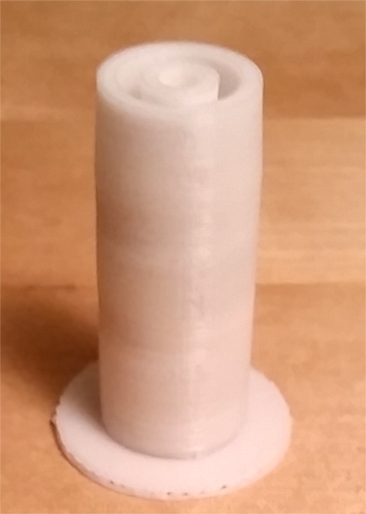
This part was created to replace a lost part on a V Strom motorcycle.
The original part was positioned inside of the handlebars and accepted an M6 screw that held the bar end weight to the handlebars. I decided to use a press fit on a 3D printed part for the ease of manufacturing and assembly. Calculations in Python were used to confirm that a 3D printed ABS part would be a reasonable solution based on stress due to press fit, pull out force of press fit and strength of threads.
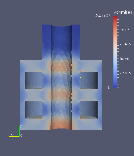
A 3D model of the part was created in FreeCAD. FEA of a simplified version of the model was analysed in ELMER. The part was then optimized by removing material based on the initial analysis and ran again.
Analysis results shown in Paraview:
FSAE Brake System
As Brake Lead, I was in charge of the design and fabrication of the brake system. My design needed to follow the overall car goals of simple and lightweight while minimizing cost.
The High level system specifications:
- Calipers: Brembo P32 2 piece calipers mounted outboard
- Rotors: Carbon steel with max diameter allowed by calipers
- Hats: CNC Machined Al
- Master Cylinders: 1 for Front & 1 for Rear sized for dynamic braking conditions
- Balance Bar: splits force between front and rear master cylinders to fine tune brake force distribution
- Brake Pedal: CNC Machined Al built to handle FSAE mandated max force
The system was successful as the car passed inspection at the FSAE competition and the brake system had no issues during the competition.
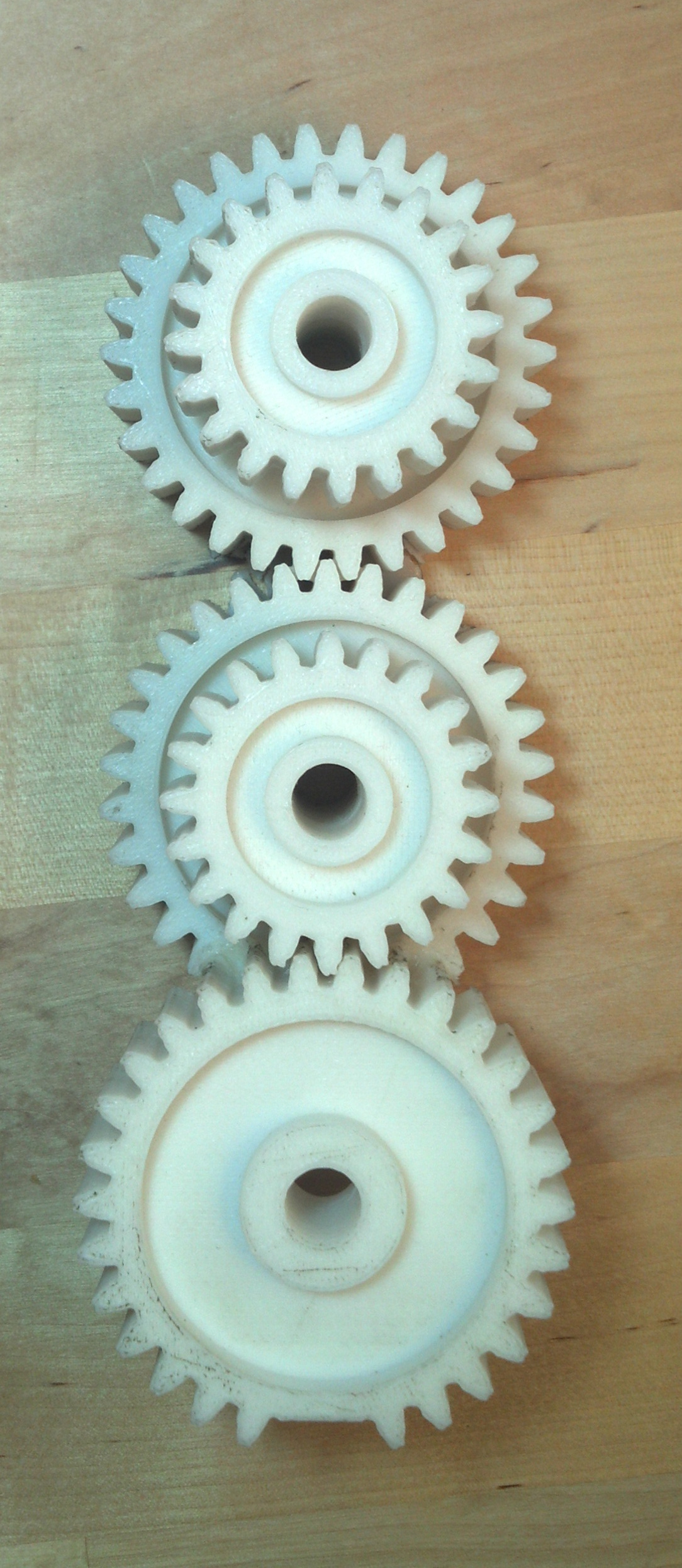
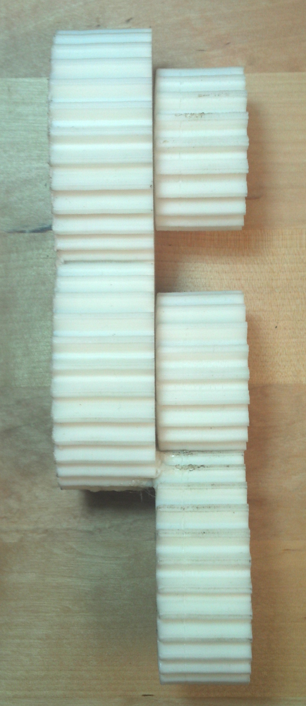
Gear Train Tap Handle
Tap handle designed to mimic a functional gear train. The prototype pictured was printed in 4 pieces to minimize supports needed during printing. The pieces were then assembled using a combination of superglue and plastic welding.
Next steps:- Investigate revising print settings to improve tooth quality
- Remove unnecessary material to lower cost and weight
- Investigate option to manufacture using CNC machine
Front view: